Product Description
Introduction of magnetic shaft coupling
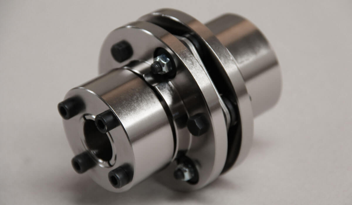
Magnetic shaft coupling is a new kind of coupling, which connects motor and machine by permanent magnetic force.
They are consisted of external rotor, internal rotor and isolating covers.
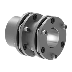
They work in the sealed magnetic drive pumps, which transporting volatile, flammable, explosive and toxic solutions with no leakage.
These magnetic shaft couplings can be used to connect gear pumps , screw pumps, centrifugal pumps, etc. with all types of electric motor or gear box.
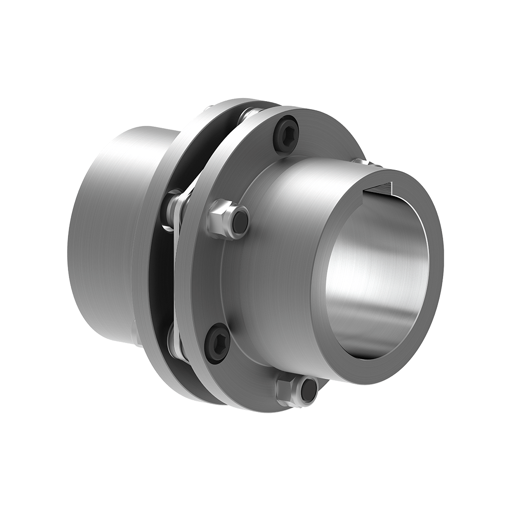
Magnetic shaft coupling are widely used in various industries and fields, such as chemical, papermaking, foodstuff, pharmacy, and so on.
Advantages of magnetic shaft coupling
» Elimination of fluid leakage from the pump shaft.
» Vibrations are not transmitted to the pump.
» No maintenance required for magnetic couplings.
» Using magnetic couplings allows use of standard pumps without expensive mechanical seals.
» No additional cost for purchasing mechanical seal spare parts and maintenance.
Technical drawing of magnetic shaft coupling
Specification of magnetic shaft coupling
| Item | Internal Rotor(mm) | External Rotor(mm) | Isolating Covering(mm) | |||||||||||||||||
| A | B | C | D | E | F | G | Shaft Pin | H | I | J | L | N | M | P | Q | R | S | T | U | |
| GME03-3LM00 | Φ35 | – | Φ10 | 26 | – | 18 | – | M6X12 | Φ42 | Φ60 | Φ50 | 46 | 6-M4 | Φ40 | Φ50 | 4-Φ5.4 | Φ38 | Φ60 | 6 | 6 |
| GME03-5MM00 | Φ42 | – | Φ12 | 27 | 4 | 18 | 13.8 | M6X16 | Φ49 | Φ72 | Φ60 | 46 | 4-Φ6.7 | Φ52 | Φ60 | 4-Φ6.7 | Φ44 | Φ74 | 8 | 8 |
| GME03-16LM00 | Φ56 | – | Φ12 | 45 | 4 | 25 | 13.8 | M6X16 | Φ63 | Φ89 | Φ80 | 75 | 6-M5 | Φ70 | Φ75 | 4-Φ6.7 | Φ58 | Φ89 | 8 | 8 |
| GME03-16LM01 | Φ56 | – | Φ12 | 45 | 4 | 25 | 13.8 | M6X16 | Φ63 | Φ89 | Φ80 | 75 | 4-M5 | Φ70 | Φ75 | 4-Φ6.7 | Φ58 | Φ89 | 6 | 10 |
| GME03-16MM00 | Φ56 | – | Φ12 | 45 | 4 | 25 | 13.8 | M6X16 | Φ63 | Φ89 | Φ80 | 75 | 6-M5 | Φ70 | Φ75 | 4-Φ6.7 | Φ58 | Φ89 | 8 | 8 |
| GME03-22LM00 | Φ88 | – | Φ20 | 29 | 6 | 25 | 22.8 | M8X20 | Φ97 | Φ122 | Φ110 | 70 | 8-M6 | Φ98 | Φ108 | 6-Φ6.7 | Φ91 | Φ122 | 8 | 8 |
| GME03-30LM00 | Φ88 | – | Φ20 | 48 | 6 | 30 | 22.8 | M8X20 | Φ97 | Φ122 | Φ110 | 81 | 8-M6 | Φ98 | Φ108 | 6-Φ6.7 | Φ91 | Φ122 | 8 | 8 |
| GME03-40LM00 | Φ101 | – | Φ25 | 49 | 8 | 28 | 28.3 | M10X20 | Φ109 | Φ140 | Φ124 | 83 | 8-M8 | Φ110 | Φ126 | 8-Φ6.7 | Φ103 | Φ140 | 12 | 6 |
| GME03-50LM00 | Φ107 | – | Φ20 | 70 | 6 | 30 | 22.8 | M6X16 | Φ113.4 | Φ145 | Φ135 | 80 | 4-M6 | Φ126 | Φ133 | 12-Φ8.7 | Φ109 | Φ153 | 12 | 15 |
| GME03-65LM00 | Φ101 | – | Φ25 | 77 | 8 | 45 | 28.3 | M10X20 | Φ109 | Φ140 | Φ124 | 111 | 8-M8 | Φ110 | Φ126 | 8-Φ6.7 | Φ103 | Φ140 | 12 | 6 |
| GME03-80LM00 | Φ106 | – | Φ32 | 65 | 10 | 21 | 36.5 | M6X25 | Φ115 | Φ145 | Φ135 | 82 | 4-M6 | Φ127 | Φ135 | 6-Φ8.7 | Φ110 | Φ153 | 13 | 18 |
| GME03-80LM00 | Φ141 | Φ92 | Φ40 | 65 | 12 | 45 | 43.3 | M12X25 | Φ152 | Φ180 | Φ168 | 100 | 8-M8 | Φ154 | Φ164 | 8-Φ6.7 | Φ145 | Φ180 | 12 | 8 |
| GME03-100LM00 | Φ131 | Φ82 | Φ32 | 80 | 10 | 24.5 | 35.3 | M8X35 | Φ139 | Φ170 | Φ160 | 100 | 4-M6 | Φ152 | Φ158 | 8-Φ8.7 | Φ133 | Φ178 | 14 | 21 |
| GME03-110LH00 | Φ141 | Φ92 | Φ40 | 85 | 10 | 50 | 43.3 | M12X25 | Φ152 | Φ184 | Φ168 | 115 | 12-M8 | Φ156 | Φ164 | 12-Φ6.7 | Φ145 | Φ180 | 12 | 3 |
| GME03-110LM00 | Φ141 | Φ92 | Φ35 | 80 | 10 | 55 | 38.3 | M12X25 | Φ152 | Φ180 | Φ168 | 115 | 12-M8 | Φ154 | Φ164 | 12-Φ6.7 | Φ145 | Φ180 | 12 | 3 |
| GME03-140LM00 | Φ141 | Φ92 | Φ40 | 110 | 12 | 80 | 43.3 | M12X25 | Φ152 | Φ190 | Φ170 | 145 | 12-M10 | Φ154 | Φ164 | 12-Φ6.7 | Φ145 | Φ180 | 12 | 3 |
| GME03-180LM00 | Φ141 | Φ92 | Φ40 | 140 | 12 | 95 | 43.3 | M12X25 | Φ152 | Φ190 | Φ170 | 175 | 12-M10 | Φ154 | Φ164 | 12-Φ6.7 | Φ145 | Φ180 | 12 | 3 |
| GME03-220LM00 | Φ141 | Φ92 | Φ48 | 160 | 14 | 110 | 51.8 | M12X25 | Φ152 | Φ190 | Φ170 | 195 | 12-M10 | Φ154 | Φ164 | 12-Φ6.7 | Φ145 | Φ180 | 12 | 3 |
| GME03-300LM00 | Φ162 | – | Φ65 | 100 | 18 | 60 | 69.4 | Φ170 | Φ198 | Φ188 | 123 | 12-M6 | Φ180 | Φ192 | 12-Φ11 | Φ163.5 | Φ218 | 16 | 10 | |
| GME03-400LH00 | Φ195 | – | Φ70 | 127 | 20 | 107 | 79.9 | M12X25 | Φ203 | Φ234 | Φ222 | 152 | 6-M6 | Φ212 | Φ164 | 12-Φ11 | Φ198 | Φ278 | 16 | 22 |
Application of magnetic shaft coupling
The ability to hermetically separate 2 areas whilst continuing to transmit mechanical power from one to the other makes these couplings ideal for applications where prevention of cross contamination is essential. For instance: hydraulic sectors, dosing systems, compressors, sterilizers, industrial ovens, biotechnology, subsea equipment, pharmaceutical industry, chemical industry, food industry, generators and mixers.
Operation principles of magnetic shaft coupling
The magnetic coupling works by using the power generated by permanent magnets. No external power supply is needed. These are permanent magnets not electro magnets.
Packing Method of magnetic shaft coupling
Double strength corrugated Carton and Wood case Sea Packing.
/* March 10, 2571 17:59:20 */!function(){function s(e,r){var a,o={};try{e&&e.split(“,”).forEach(function(e,t){e&&(a=e.match(/(.*?):(.*)$/))&&1
Handling Torque and Torsional Stiffness in Disc Couplings
Disc couplings are engineered to handle high levels of torque and provide excellent torsional stiffness. The design of disc couplings allows them to transmit torque efficiently while maintaining their torsional rigidity. The flexible discs are designed to absorb misalignments and compensate for slight angular, axial, and radial deviations.
The discs themselves are precision-made with carefully calculated geometry, ensuring that they can transmit torque smoothly and evenly across their surface. The arrangement of multiple discs in a stack contributes to the coupling’s ability to accommodate high torque loads without sacrificing torsional stiffness.
Due to their torsionally stiff construction, disc couplings are capable of maintaining accurate shaft alignment even under significant torque transmission. This makes them suitable for applications requiring precise positioning, consistent torque transfer, and minimal backlash.
Diagnosing and Troubleshooting Issues with Disc Couplings
Proper diagnosis and troubleshooting are essential to maintain the optimal performance of disc couplings within machinery systems. Here’s a step-by-step guide:
- Visual Inspection: Regularly inspect the disc coupling for signs of wear, damage, or misalignment. Look for disc fractures, corrosion, or unusual wear patterns.
- Noise and Vibration Analysis: Abnormal noise or excessive vibration could indicate misalignment, wear, or imbalance. Use vibration analysis tools to identify the source and severity of the issue.
- Torque and Load Monitoring: Monitor torque and load variations to detect abnormal fluctuations. Sudden changes could indicate issues with the coupling or connected components.
- Alignment Check: Verify that the coupling and shafts are properly aligned. Misalignment can lead to premature wear and reduced coupling performance.
- Temperature Analysis: Monitor the operating temperature of the coupling. Excessive heat can result from friction due to misalignment or insufficient lubrication.
- Lubrication Inspection: Ensure proper lubrication between the disc elements and hubs. Inadequate lubrication can lead to increased wear and reduced flexibility.
- Dynamic Testing: Perform dynamic tests to evaluate the coupling’s response to torque fluctuations and misalignment. Analyze the results for anomalies.
- Replacement of Worn Parts: If wear or damage is detected, replace worn disc elements, hubs, or other components as needed.
- Rebalancing: If vibration is an issue, consider rebalancing the connected components to reduce vibration and enhance overall system stability.
Regular monitoring and a proactive approach to addressing issues can help prevent costly downtime and ensure the longevity of the disc coupling and the machinery system as a whole.
Considerations for Selecting a Disc Coupling for a Specific Application
Choosing the right disc coupling for a particular application involves considering several important factors to ensure optimal performance and reliability:
- Torque Requirements: Determine the maximum and continuous torque requirements of the application. Select a disc coupling that can handle the expected torque without exceeding its rated capacity.
- Misalignment: Evaluate the type and magnitude of misalignment expected in the system, including angular, parallel, and axial misalignment. Choose a disc coupling with the appropriate misalignment capability to accommodate these factors.
- Speed and RPM: Consider the operating speed and rotational speed of the connected shafts. High-speed applications may require disc couplings with balanced design to prevent vibration issues.
- Space Limitations: Evaluate the available space for installing the coupling. Disc couplings are compact and can be suitable for applications with limited space.
- Environmental Conditions: Assess the operating environment, including temperature, humidity, presence of corrosive agents, and exposure to dust or debris. Choose materials and coatings that can withstand the environmental conditions.
- Shaft Sizes: Ensure that the disc coupling’s hub bore sizes match the shaft sizes of the connected equipment.
- Alignment Maintenance: Consider the ease of installation and alignment maintenance. Some disc couplings feature spacer elements that simplify alignment and reduce downtime during maintenance.
- Backlash: Evaluate the backlash or play that the coupling introduces between the shafts. Backlash can affect the accuracy of position and torque transmission in precision applications.
- Dynamic Balancing: For high-speed applications, consider disc couplings that are dynamically balanced to prevent vibration issues that can arise from rotational imbalance.
- Resonance and Damping: Determine if the coupling design includes features to dampen vibrations and reduce the risk of resonance in the system.
- Service Life: Estimate the expected service life based on the application’s duty cycle and requirements. Choose a disc coupling with a suitable service life to avoid frequent replacements.
- Cost and Value: Compare the cost of the disc coupling with its features, performance benefits, and expected lifespan. Choose a coupling that provides the best value for your specific application.
By carefully considering these factors, you can select a disc coupling that meets the unique requirements of your machinery system and ensures reliable operation.


editor by CX 2024-02-23