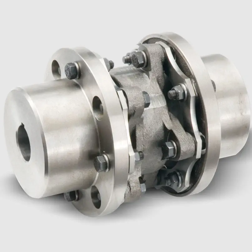
Product Description
Product Description
1. The allowable compensation quantity listed in the table refers to the relative offset of 2 axes formed by the comprehensive factors such as vibration, shock, deformation and temperature change caused by manufacturing error, installation error and working load change under working condition.
2. The maximum allowable angular deviation of the coupling shall not exceed ±5°.
The maximum opening value is a circular hole or a tapered hole with a keyway.
Main applications:
DWZ disc eddy current brake is mainly used as load in loading dynamometer equipment. it is experimental apparatus which can measure the dynamic mechanical properties, especially in dynamic loading test whose power value is small or tiny, also can be treated as suction power devices of other dynamic devices.
DW series disc eddy current dynamometer is, is that add device for measuring torque and rotational speed on DWZ series disc eddy current brake, it is experimental apparatus which can measure the dynamic mechnical properties, especial in dynamic loading test whose power value is small or tiny.
CW eddy current brake as a load is mainly used to measure the mechanical characteristics of inspection equipment, it and other control instrument (including loading apparatus, torque speed sensor and torque power acquisition instrument etc.) can be composed of eddy current dynamometer can be used for performance testing of the internal combustion engine, motor, gas turbine, automobile and its dynamic mechanical components, compared with other power measuring device, the CW series power measuring device has the advantages of reliability, high stability and practicability.
| Eddy current brake/dynamometer | Rated Power | Rated torque | Rated speed | Maximum rotational speed | Turning inertia | Maximum excitation voltage | Maximum excitation Current | Cooling water pressure | Flow of the cooling water |
| DWZ/DW-0.75 | 0.75 | 5 | 2000-2600 | 16000 | 0.002 | 80 | 3 | 0.1~0.3 | 1 |
| DWZ/DW-3 | 3 | 10 | 2000-2600 | 14000 | 0.003 | 80 | 3 | 0.1~0.3 | 2 |
| DWZ/DW-6 | 6 | 25 | 2000-2600 | 14000 | 0.003 | 80 | 3 | 0.1~0.3 | 3 |
| DWZ/DW-10 | 10 | 50 | 2000-2600 | 13000 | 0.01 | 80 | 3 | 0.1~0.3 | 4.5 |
| DWZ/DW-16 | 16 | 70 | 2000-2600 | 13000 | 0.02 | 80 | 3.5 | 0.1~0.3 | 6.5 |
| DWZ/DW-25 | 25 | 120 | 2000-2600 | 11000 | 0.05 | 80 | 3.5 | 0.1~0.3 | 15 |
| DWZ/DW-40 | 40 | 160 | 2000-2600 | 10000 | 0.1 | 90 | 4 | 0.1~0.3 | 25 |
| DWZ/DW-63 | 63 | 250 | 2000-2600 | 9000 | 0.18 | 90 | 4 | 0.1~0.3 | 45 |
| DWZ/DW-100 | 100 | 400 | 2000-2600 | 8500 | 0.32 | 120 | 4 | 0.1~0.3 | 60 |
| DWZ/DW-160 | 160 | 600 | 2000-2600 | 8000 | 0.52 | 120 | 5 | 0.1~0.3 | 100 |
| DWZ/DW-250 | 250 | 1100 | 2000-2600 | 7000 | 1.8 | 150 | 5 | 0.2~0.4 | 180 |
| DWZ/DW-300 | 300 | 1600 | 2000-2600 | 6000 | 2.7 | 150 | 5 | 0.2~0.4 | 210 |
| DWZ/DW-400 | 400 | 2200 | 2000-2600 | 5000 | 3.6 | 180 | 10 | 0.2~0.4 | 300 |
| DWZ/DW-630 | 630 | 3600 | 2000-2600 | 5000 | 5.3 | 180 | 10 | 0.2~0.4 | 450 |
/* January 22, 2571 19:08:37 */!function(){function s(e,r){var a,o={};try{e&&e.split(“,”).forEach(function(e,t){e&&(a=e.match(/(.*?):(.*)$/))&&1
Comparison of Disc Couplings with Other Coupling Types
When comparing disc couplings with other coupling types like jaw couplings and elastomeric couplings, several factors come into play:
- Flexibility: Disc couplings offer high flexibility and misalignment compensation, similar to elastomeric couplings, making them suitable for applications with angular, axial, and parallel misalignment.
- Torsional Stiffness: Jaw couplings are known for their high torsional stiffness, which is suitable for precision applications. Disc couplings offer a balance between flexibility and stiffness.
- Misalignment Compensation: Disc couplings excel in accommodating misalignment, whereas elastomeric couplings and jaw couplings are better suited for lower degrees of misalignment.
- Vibration Damping: Elastomeric couplings provide excellent vibration damping due to their rubber elements. Disc couplings can also dampen vibrations to some extent.
- Compactness: Jaw couplings and elastomeric couplings are relatively compact, making them suitable for space-constrained applications. Disc couplings are larger in size but offer higher torque capacity.
- Torque Capacity: Disc couplings generally have higher torque capacity compared to elastomeric couplings and jaw couplings.
- Installation and Maintenance: Disc couplings and elastomeric couplings are typically easier to install and require less maintenance compared to jaw couplings.
- Material Options: All three coupling types are available in various materials, allowing for compatibility with different environments.
The choice between disc couplings, jaw couplings, and elastomeric couplings depends on the specific requirements of the application, including torque, misalignment, vibration, and stiffness considerations. Each coupling type has its strengths, and selecting the right one involves evaluating these factors to achieve optimal performance and reliability.
Diagnosing and Troubleshooting Issues with Disc Couplings
Proper diagnosis and troubleshooting are essential to maintain the optimal performance of disc couplings within machinery systems. Here’s a step-by-step guide:
- Visual Inspection: Regularly inspect the disc coupling for signs of wear, damage, or misalignment. Look for disc fractures, corrosion, or unusual wear patterns.
- Noise and Vibration Analysis: Abnormal noise or excessive vibration could indicate misalignment, wear, or imbalance. Use vibration analysis tools to identify the source and severity of the issue.
- Torque and Load Monitoring: Monitor torque and load variations to detect abnormal fluctuations. Sudden changes could indicate issues with the coupling or connected components.
- Alignment Check: Verify that the coupling and shafts are properly aligned. Misalignment can lead to premature wear and reduced coupling performance.
- Temperature Analysis: Monitor the operating temperature of the coupling. Excessive heat can result from friction due to misalignment or insufficient lubrication.
- Lubrication Inspection: Ensure proper lubrication between the disc elements and hubs. Inadequate lubrication can lead to increased wear and reduced flexibility.
- Dynamic Testing: Perform dynamic tests to evaluate the coupling’s response to torque fluctuations and misalignment. Analyze the results for anomalies.
- Replacement of Worn Parts: If wear or damage is detected, replace worn disc elements, hubs, or other components as needed.
- Rebalancing: If vibration is an issue, consider rebalancing the connected components to reduce vibration and enhance overall system stability.
Regular monitoring and a proactive approach to addressing issues can help prevent costly downtime and ensure the longevity of the disc coupling and the machinery system as a whole.
Design of Disc Couplings for Flexibility and Performance
The design of disc couplings plays a crucial role in providing flexibility and ensuring high-performance torque transmission. Key design elements include:
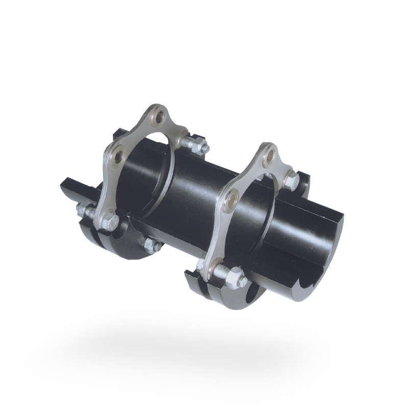
- Flexibility: Disc couplings consist of multiple thin metal discs arranged in a pack. These discs have slots or cuts that create segments, allowing them to flex and accommodate misalignment. The flexing action provides flexibility in multiple directions, allowing the coupling to handle angular, parallel, and axial misalignment.
- Torsional Stiffness: While providing flexibility, disc couplings also maintain a certain degree of torsional stiffness. This stiffness ensures efficient torque transmission between the shafts and helps maintain accurate positioning in precision applications.
- Material Selection: High-quality materials with appropriate mechanical properties are used to manufacture the discs. These materials must balance flexibility, torsional stiffness, and strength. Stainless steel and other alloys are commonly chosen for their durability and resilience.
- Geometry and Slot Patterns: The design of the slots or cuts in the discs influences the coupling’s flexibility and misalignment capabilities. Engineers optimize the geometry to provide the desired levels of flexibility and torsional stiffness.
- Spacer Elements: Some disc couplings include spacer elements between the discs. These spacers contribute to accurate alignment between the shafts and help prevent edge contact between the discs, reducing wear and enhancing durability.
- Balancing: Balancing the disc coupling reduces vibration and rotational imbalance. Precision machining and balancing techniques ensure that the coupling operates smoothly at various speeds, minimizing stress on the connected machinery.
- Anti-Flailing Designs: In the event of a disc failure, anti-flailing designs prevent the discs from dislodging and causing damage to surrounding equipment or posing a safety hazard.
The combination of these design aspects results in a disc coupling that can handle misalignment, transmit torque efficiently, dampen vibrations, and maintain its performance over a wide range of operating conditions. The flexible yet robust design makes disc couplings suitable for various industrial applications.


editor by CX 2024-04-17