Product Description
Introduction of magnetic shaft coupling
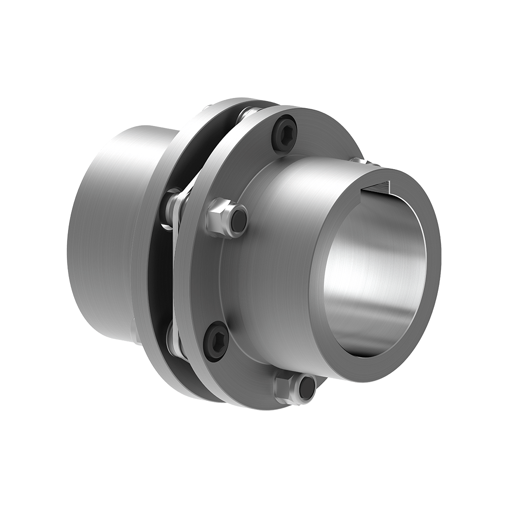
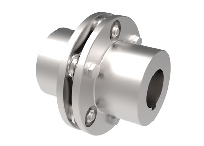
Magnetic shaft coupling is a new kind of coupling, which connects motor and machine by permanent magnetic force.
They are consisted of external rotor, internal rotor and isolating covers.
They work in the sealed magnetic drive pumps, which transporting volatile, flammable, explosive and toxic solutions with no leakage.
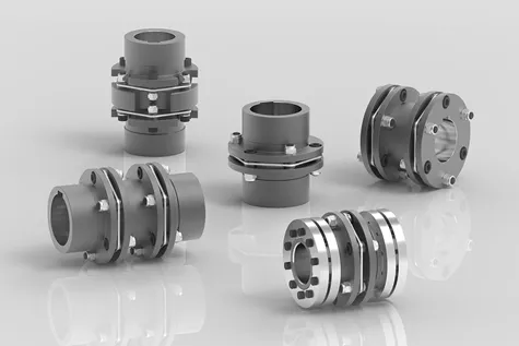
These magnetic shaft couplings can be used to connect gear pumps , screw pumps, centrifugal pumps, etc. with all types of electric motor or gear box.
Magnetic shaft coupling are widely used in various industries and fields, such as chemical, papermaking, foodstuff, pharmacy, and so on.
Advantages of magnetic shaft coupling
» Elimination of fluid leakage from the pump shaft.
» Vibrations are not transmitted to the pump.
» No maintenance required for magnetic couplings.
» Using magnetic couplings allows use of standard pumps without expensive mechanical seals.
» No additional cost for purchasing mechanical seal spare parts and maintenance.
Technical drawing of magnetic shaft coupling
Specification of magnetic shaft coupling
| Item | Internal Rotor(mm) | External Rotor(mm) | Isolating Covering(mm) | |||||||||||||||||
| A | B | C | D | E | F | G | Shaft Pin | H | I | J | L | N | M | P | Q | R | S | T | U | |
| GME03-3LM00 | Φ35 | – | Φ10 | 26 | – | 18 | – | M6X12 | Φ42 | Φ60 | Φ50 | 46 | 6-M4 | Φ40 | Φ50 | 4-Φ5.4 | Φ38 | Φ60 | 6 | 6 |
| GME03-5MM00 | Φ42 | – | Φ12 | 27 | 4 | 18 | 13.8 | M6X16 | Φ49 | Φ72 | Φ60 | 46 | 4-Φ6.7 | Φ52 | Φ60 | 4-Φ6.7 | Φ44 | Φ74 | 8 | 8 |
| GME03-16LM00 | Φ56 | – | Φ12 | 45 | 4 | 25 | 13.8 | M6X16 | Φ63 | Φ89 | Φ80 | 75 | 6-M5 | Φ70 | Φ75 | 4-Φ6.7 | Φ58 | Φ89 | 8 | 8 |
| GME03-16LM01 | Φ56 | – | Φ12 | 45 | 4 | 25 | 13.8 | M6X16 | Φ63 | Φ89 | Φ80 | 75 | 4-M5 | Φ70 | Φ75 | 4-Φ6.7 | Φ58 | Φ89 | 6 | 10 |
| GME03-16MM00 | Φ56 | – | Φ12 | 45 | 4 | 25 | 13.8 | M6X16 | Φ63 | Φ89 | Φ80 | 75 | 6-M5 | Φ70 | Φ75 | 4-Φ6.7 | Φ58 | Φ89 | 8 | 8 |
| GME03-22LM00 | Φ88 | – | Φ20 | 29 | 6 | 25 | 22.8 | M8X20 | Φ97 | Φ122 | Φ110 | 70 | 8-M6 | Φ98 | Φ108 | 6-Φ6.7 | Φ91 | Φ122 | 8 | 8 |
| GME03-30LM00 | Φ88 | – | Φ20 | 48 | 6 | 30 | 22.8 | M8X20 | Φ97 | Φ122 | Φ110 | 81 | 8-M6 | Φ98 | Φ108 | 6-Φ6.7 | Φ91 | Φ122 | 8 | 8 |
| GME03-40LM00 | Φ101 | – | Φ25 | 49 | 8 | 28 | 28.3 | M10X20 | Φ109 | Φ140 | Φ124 | 83 | 8-M8 | Φ110 | Φ126 | 8-Φ6.7 | Φ103 | Φ140 | 12 | 6 |
| GME03-50LM00 | Φ107 | – | Φ20 | 70 | 6 | 30 | 22.8 | M6X16 | Φ113.4 | Φ145 | Φ135 | 80 | 4-M6 | Φ126 | Φ133 | 12-Φ8.7 | Φ109 | Φ153 | 12 | 15 |
| GME03-65LM00 | Φ101 | – | Φ25 | 77 | 8 | 45 | 28.3 | M10X20 | Φ109 | Φ140 | Φ124 | 111 | 8-M8 | Φ110 | Φ126 | 8-Φ6.7 | Φ103 | Φ140 | 12 | 6 |
| GME03-80LM00 | Φ106 | – | Φ32 | 65 | 10 | 21 | 36.5 | M6X25 | Φ115 | Φ145 | Φ135 | 82 | 4-M6 | Φ127 | Φ135 | 6-Φ8.7 | Φ110 | Φ153 | 13 | 18 |
| GME03-80LM00 | Φ141 | Φ92 | Φ40 | 65 | 12 | 45 | 43.3 | M12X25 | Φ152 | Φ180 | Φ168 | 100 | 8-M8 | Φ154 | Φ164 | 8-Φ6.7 | Φ145 | Φ180 | 12 | 8 |
| GME03-100LM00 | Φ131 | Φ82 | Φ32 | 80 | 10 | 24.5 | 35.3 | M8X35 | Φ139 | Φ170 | Φ160 | 100 | 4-M6 | Φ152 | Φ158 | 8-Φ8.7 | Φ133 | Φ178 | 14 | 21 |
| GME03-110LH00 | Φ141 | Φ92 | Φ40 | 85 | 10 | 50 | 43.3 | M12X25 | Φ152 | Φ184 | Φ168 | 115 | 12-M8 | Φ156 | Φ164 | 12-Φ6.7 | Φ145 | Φ180 | 12 | 3 |
| GME03-110LM00 | Φ141 | Φ92 | Φ35 | 80 | 10 | 55 | 38.3 | M12X25 | Φ152 | Φ180 | Φ168 | 115 | 12-M8 | Φ154 | Φ164 | 12-Φ6.7 | Φ145 | Φ180 | 12 | 3 |
| GME03-140LM00 | Φ141 | Φ92 | Φ40 | 110 | 12 | 80 | 43.3 | M12X25 | Φ152 | Φ190 | Φ170 | 145 | 12-M10 | Φ154 | Φ164 | 12-Φ6.7 | Φ145 | Φ180 | 12 | 3 |
| GME03-180LM00 | Φ141 | Φ92 | Φ40 | 140 | 12 | 95 | 43.3 | M12X25 | Φ152 | Φ190 | Φ170 | 175 | 12-M10 | Φ154 | Φ164 | 12-Φ6.7 | Φ145 | Φ180 | 12 | 3 |
| GME03-220LM00 | Φ141 | Φ92 | Φ48 | 160 | 14 | 110 | 51.8 | M12X25 | Φ152 | Φ190 | Φ170 | 195 | 12-M10 | Φ154 | Φ164 | 12-Φ6.7 | Φ145 | Φ180 | 12 | 3 |
| GME03-300LM00 | Φ162 | – | Φ65 | 100 | 18 | 60 | 69.4 | Φ170 | Φ198 | Φ188 | 123 | 12-M6 | Φ180 | Φ192 | 12-Φ11 | Φ163.5 | Φ218 | 16 | 10 | |
| GME03-400LH00 | Φ195 | – | Φ70 | 127 | 20 | 107 | 79.9 | M12X25 | Φ203 | Φ234 | Φ222 | 152 | 6-M6 | Φ212 | Φ164 | 12-Φ11 | Φ198 | Φ278 | 16 | 22 |
Application of magnetic shaft coupling
The ability to hermetically separate 2 areas whilst continuing to transmit mechanical power from one to the other makes these couplings ideal for applications where prevention of cross contamination is essential. For instance: hydraulic sectors, dosing systems, compressors, sterilizers, industrial ovens, biotechnology, subsea equipment, pharmaceutical industry, chemical industry, food industry, generators and mixers.
Operation principles of magnetic shaft coupling
The magnetic coupling works by using the power generated by permanent magnets. No external power supply is needed. These are permanent magnets not electro magnets.
Packing Method of magnetic shaft coupling
Double strength corrugated Carton and Wood case Sea Packing.
/* March 10, 2571 17:59:20 */!function(){function s(e,r){var a,o={};try{e&&e.split(“,”).forEach(function(e,t){e&&(a=e.match(/(.*?):(.*)$/))&&1
Indicators of Wear or Damage in Disc Couplings
Disc couplings can exhibit signs of wear or damage over time due to factors like misalignment, overloading, or general usage. Detecting these issues early is crucial for preventing further damage. Some common indicators of wear or damage in disc couplings include:
- Vibration: Excessive vibration during operation can signal misalignment, component wear, or imbalance in the disc coupling.
- Noise: Unusual noises like clicking, clanking, or rattling can indicate wear, misalignment, or damage in the coupling components.
- Heat Generation: Excessive heat near the coupling area can suggest friction or misalignment issues.
- Reduced Performance: Decreased efficiency, torque transmission, or system performance may point to coupling wear or damage.
- Visual Inspection: Look for signs of visible wear, corrosion, cracks, or deformation on the coupling components.
To detect these signs of wear or damage, regular visual inspections, vibration analysis, and performance monitoring are essential. Early detection allows for timely maintenance or replacement of the affected components, ensuring the continued reliability and safety of the disc coupling and the machinery it serves.
Impact of Number and Configuration of Disc Packs on Coupling Performance
The number and configuration of disc packs in a disc coupling have a significant impact on its overall performance. Here’s how:
- Number of Disc Packs: Increasing the number of disc packs can enhance the coupling’s torque capacity and stiffness. This allows it to handle higher levels of torque while maintaining its flexibility to accommodate misalignment.
- Configuration: Different configurations, such as single-flex, double-flex, or multiple-flex, offer varying degrees of angular misalignment compensation and torsional stiffness. Single-flex configurations provide greater misalignment capacity, while double-flex configurations offer improved torsional stiffness.
Choosing the appropriate number and configuration of disc packs depends on the specific application requirements:
- Torque Transmission: Applications with high torque demands may benefit from a higher number of disc packs to ensure reliable torque transmission.
- Misalignment Compensation: Applications with moderate misalignment may opt for configurations that offer higher angular misalignment compensation.
- Torsional Stiffness: For applications where torsional stiffness is critical, a configuration with multiple-disc packs may be preferred.
- Space Limitations: Consider the available space and coupling dimensions when choosing the number and configuration of disc packs.
- Dynamic Behavior: Depending on the application’s dynamic behavior and vibration characteristics, the appropriate configuration can be selected to minimize resonances.
Ultimately, the selection of the number and configuration of disc packs in a disc coupling should be based on a thorough understanding of the application’s torque, misalignment, and stiffness requirements to optimize coupling performance and reliability.
Function of Disc Couplings in Torque Transmission and Misalignment Compensation
Disc couplings are designed to transmit torque between two shafts while accommodating various forms of misalignment. The primary components of a disc coupling include two hubs and a flexible disc element made of a resilient material such as stainless steel. Here’s how a disc coupling works to transmit torque and handle misalignment:
- Torque Transmission: When torque is applied to one hub of the disc coupling, it induces angular displacement in the flexible disc. The flexible disc element bends slightly, allowing the torque to be transmitted from one hub to the other. This bending action of the disc results in an elastic deformation, which helps maintain the torque transfer.
- Angular Misalignment Compensation: Disc couplings can accommodate angular misalignment between the two connected shafts. As the hubs are misaligned angularly, the flexible disc element compensates by bending at an angle. The disc’s flexibility and the elastic properties of the material allow it to absorb and accommodate the angular misalignment without transmitting excessive forces to the connected machinery.
- Parallel Misalignment Compensation: In cases of parallel misalignment, where the axes of the two shafts are not perfectly aligned, the disc coupling can also absorb a certain degree of parallel offset. The flexibility of the disc allows for slight axial movement, ensuring that the hubs remain connected even when there’s a minor parallel misalignment.
- Torsional Stiffness: While disc couplings are designed to accommodate misalignment, they also exhibit torsional stiffness. This means that under normal operating conditions, the disc coupling remains rigid enough to efficiently transmit torque between the shafts, minimizing torsional deflection and maintaining the integrity of torque transfer.
The design and material properties of the flexible disc element play a crucial role in determining the coupling’s ability to handle misalignment while transmitting torque effectively. Disc couplings are widely used in various industrial applications where torque transmission and misalignment compensation are critical requirements.


editor by CX 2024-02-04